Product Categories
- Arduino Shields
- Breakout Boards
- CAN (Controller Area Network)
- Connectors and Interconnect
- Drivers, DACs & Outputs
- FIRST Robotics Competition
- Formula SAE
- Hardware
- Interface and Logging
- Power Supplies and Distribution
- Qwiic Connect System
- R3aktor Data Acquisition
- Sensors
- Software
- Switches, Encoders, & Buttons
- Temperature Measurement
- Wire
- Discontinued
Tech Article Categories
Posted: March 5, 2025
Modified: March 5, 2025
Home > Tech Article Categories > Interface and Communication > Controller/Target I2C Communication with R3aktor
Controller/Target I2C Communication with R3aktor
Introduction
I2C is a digital protocol commonly used to communicate between a host/controller and other ICs - generally sensors or memory. The controller generally initiates communication and the target/slave device responds. The SAMD21 micro used by R3aktor can act as either the controller or the target.
In this example, one R3aktor acts as the target and responds to read requests from a second R3aktor, the controller.
Parts List
For this project, you will need:
- (x2) R3aktor M0 Logger Board
- (x2) USB-C cables
- (x1) Solderless breadboard
- (x4) 10kΩ resistors
- (x1) Female to female jumper cable
- (x2) Male to male jumper cables
- (x6) Male to female jumper cables
Hardware Setup
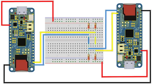
Create the circuit. Connect the GND pins on the R3aktor boards together. On one R3aktor board, connect the 3V3 pin to the red (+) rail on the breadboard. Connect both the SDA and SCL pins to different rows on the breadboard. Connect a resistor from the SDA row to the red (+) rail. Do the same for the SCL row. Repeat these steps for the other R3aktor board, but on the opposite side of the breadboard. Connect each R3aktor’s SDA and SCL rows together. The finished circuit should look like the diagram below. Note that this example includes two resistors on the SDA and SCL lines, but generally only one is recommended for each line.
Open the Arduino IDE. For this project, you will need to utilize the Arduino Wire library which comes pre-installed with the IDE, so there is no library installation you need to do. The Wire library is the primary library used to interact with the I2C peripheral on most Arduino devices. Create two new sketches. One will be for the Controller code and the other will be for the Target code.
Controller Software
In the controller sketch, paste this code:
- #include <Wire.h>
- int value = 0;
- void setup() {
- Wire.begin();
- Serial.begin(9600);
- }
- void loop() {
- Wire.beginTransmission(9);
- Wire.write(value);
- Wire.endTransmission();
- Serial.println("Value written");
- value++;
- if (value > 2) value = 0;
- delay(5000);
- }
Target Software
In the sketch for the target device, paste this:
- #include <Wire.h>
- int value = 0;
- void setup() {
- pinMode(LED_BUILTIN, OUTPUT);
- Wire.begin(9);
- Wire.onReceive(receiveEvent); // method to run when an event is received
- Serial.begin(9600);
- }
- void receiveEvent(int bytes) {
- value = Wire.read();
- Serial.println("event received");
- }
- void loop() {
- if (value == 0) {
- digitalWrite(LED_BUILTIN, HIGH);
- delay(200);
- digitalWrite(LED_BUILTIN, LOW);
- delay(200);
- }
- if (value == 1) {
- digitalWrite(LED_BUILTIN, HIGH);
- delay(500);
- digitalWrite(LED_BUILTIN, LOW);
- delay(500);
- }
- if (value == 2) {
- digitalWrite(LED_BUILTIN, HIGH);
- delay(1000);
- digitalWrite(LED_BUILTIN, LOW);
- delay(1000);
- }
- }
Deploy Software to Both Devices
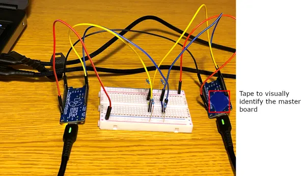
Connect both R3aktor boards to your computer via the USB-C cables. Designate one board as the Controller board. The other board will be the Target.
Upload the Controller code to the Controller R3aktor board. Upload the Target code to the Target board. If uploading to both boards from the same computer, ensure you have selected the correct COM port for the R3aktor board you wish to upload to. Once the code is uploaded, you will be able to see the target R3aktor’s built-in LED flash at a decreasing frequency every five seconds. This is because the slave board is receiving a value generated by the controller and sent via the I2Cprotocol.
 R3actor M0 Logger with SD Socket and Battery Charger
 R3aktor Core K-Type Thermocouple Data Acquisition Board
 R3aktor Core Universal Thermocouple Data Acquisition Board