Product Categories
- Arduino Shields
- Breakout Boards
- CAN (Controller Area Network)
- Connectors and Interconnect
- Drivers, DACs & Outputs
- FIRST Robotics Competition
- Formula SAE
- Hardware
- Interface and Logging
- Power Supplies and Distribution
- Qwiic Connect System
- R3aktor Data Acquisition
- Sensors
- Software
- Switches, Encoders, & Buttons
- Temperature Measurement
- Wire
- Discontinued
Tech Article Categories
Table of Contents
Posted: June 9, 2024
Modified: June 9, 2024
Home > Tech Article Categories > FRC and Robotics > 3D Printed RC Transmitter
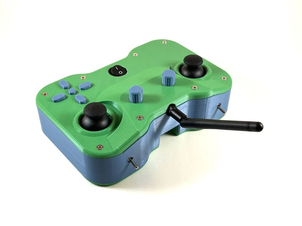
3D Printed RC Transmitter
Preperation
Gather the materials:
- Hardware
- (x4) m2x8 pan head screws
- (x4) m2 nuts
- (x14) m3x8 pan head screws
- (x10) m3x12 pan head screws
- (x24) m3 nuts
- (x8) m3x20 hex standoffs
- (x14) m3x16 countersunk screws
- (x2) m3x20 countersunk screws
- Electronics
- (x1) PWF R3aktor M0 Logger
- (x2) PWF IFB-40001 I2C Encoders
- (x2) PWF IFB-40002 I2C Joysticks
- (x1) PWF IFB-40003 I2C Buttons
- (x2) PWF IFB-40004 I2C Switches
- (x1) PWF IFB-40005 Power Switch
- (x1) NRF24L01+PA+LNA RF Module
- (x1) 10uF Ceramic capacitor
- (x1) 1s 3.7v 2000mAh Battery
- (x7) QWIIC Cable
- (x1) male to male JST cable
- (x7) male to male pin header jumper cables
- (x1) row of 12 angled pin headers
- (x1) row of 16 angled pin headers
Print the parts (download link for all parts):
- (x1) Top
- (x1) Outer Wall
- (x1) Bottom
- (x4) Button
- (x1) Middle Button
- (x2) Encoder Knob
- (x1) Radio Enclosure
- (x1) Button Bracket
- (x1) Battery Enclosure
- (x1) Joystick Bracket - right
- (x1) Joystick Bracket - left
- (x1) Encoder Bracket
- (x1) Power Switch Bracket
- (x1) Toggle Switch Bracket - right
- (x1) Toggle Switch Bracket - left
- (x4) Small Spacer
- (x1) Switch Spacer - right
- (x1) Switch Spacer - left
- (x1) Lower Power Switch Spacer
- (x1) Upper Power Switch Spacer
- (x1) Lower Button Bracket Spacer
- (x1) Upper Button Bracket Spacer - right
- (x1) Upper Button Bracket Spacer - left
- (x16) Standoff
Solder the PCB componets:
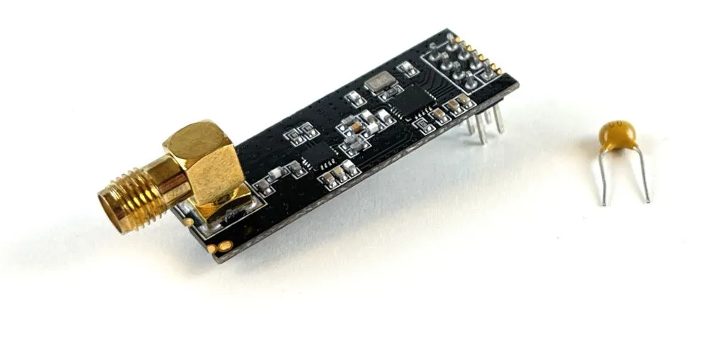
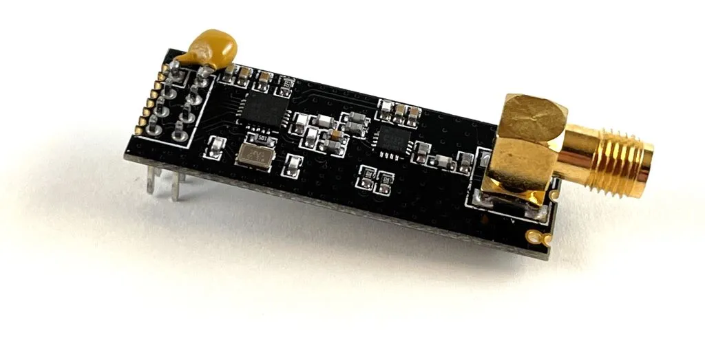
Solder the 10uF ceramic capacitor to the positive and negative terminals of the radio module. Keep the form factor as small as possible so the radio module will fit in the 3D printed enclosure.
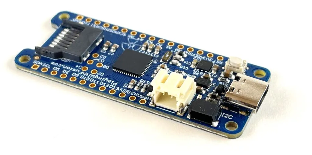
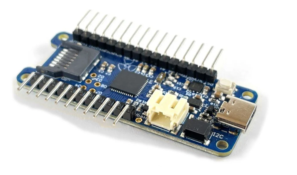
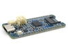
Solder the angled pin headers to the R3aktor board.
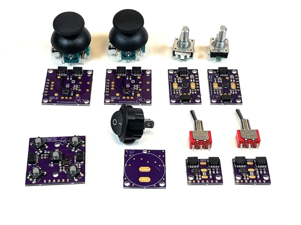
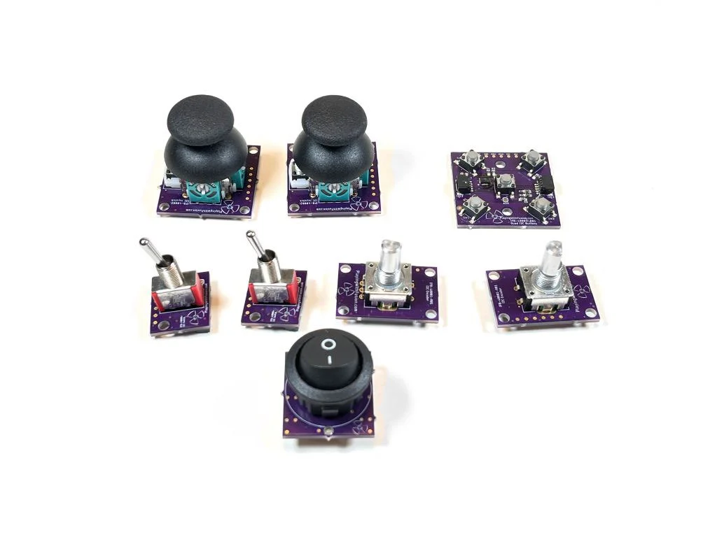
Gather all the Playing with Fusion PCBs and their components. Solder each component onto each board. Take special care with the power switch PCB and the toggle switch PCBs so that the components are as close to square to the PCB as possible.
Assembly
Step 1:
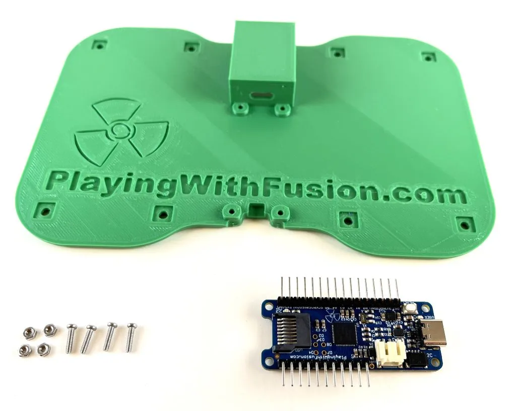
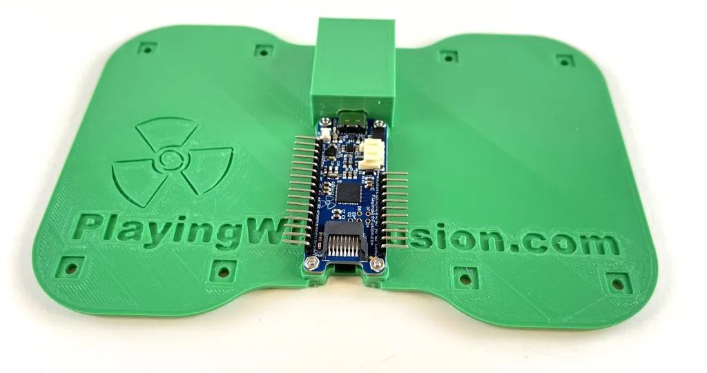
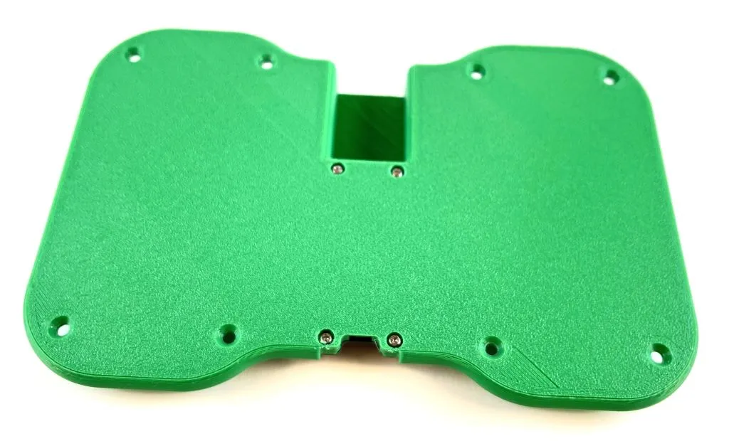
Gather 4 M2x8 pan head screws, 4 M2 nuts, the R3aktor, and the bottom. Place the R3aktor onto the raised cylinders in the center of the bottom. You may need to slide the USB-C port into the USB-C slot first, and then fit the R3aktor into place. Use the M2 hardware to secure the R3ktor to the bottom.
Step 2:
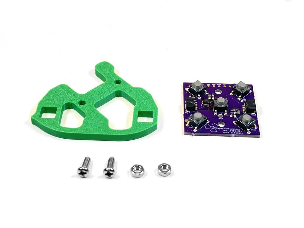
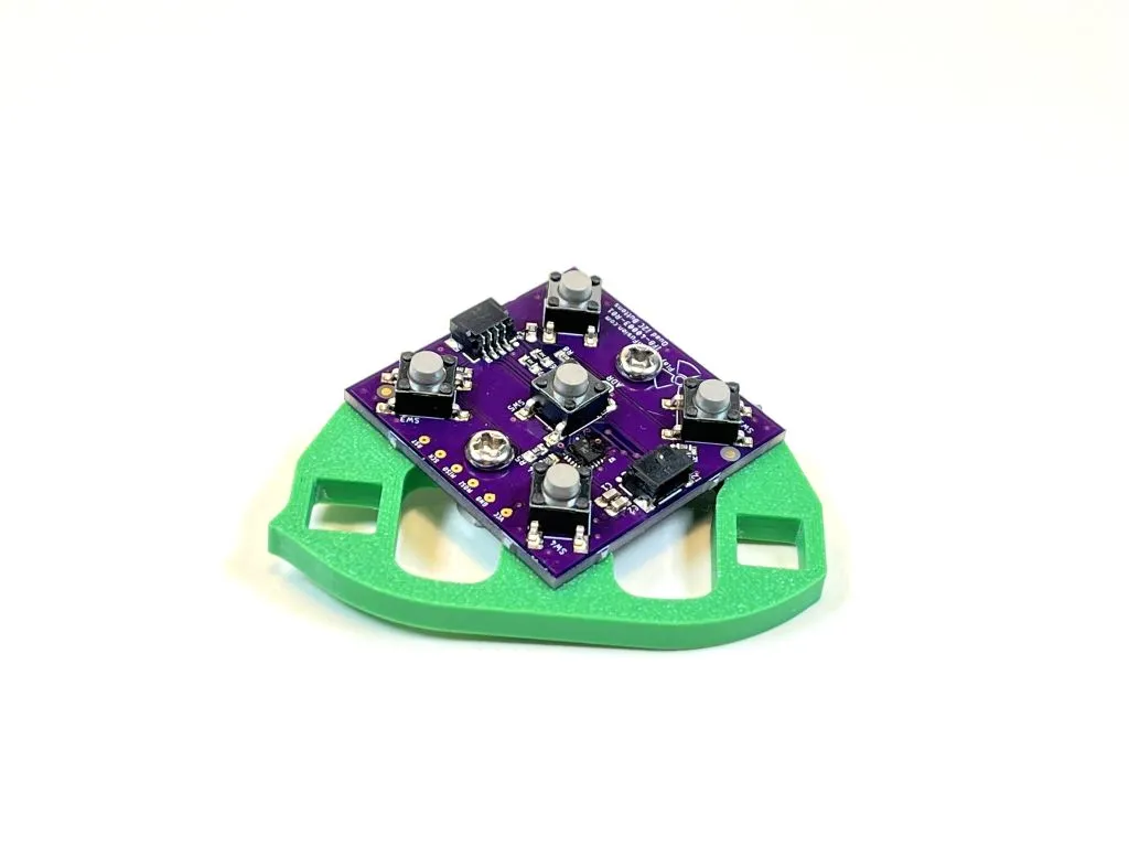
Assemble the button PCB to the button bracket using 2 m3x8 screws and 2 m3 nuts. Make sure the button PCB goes onto the right side of the bracket.
Step 3:
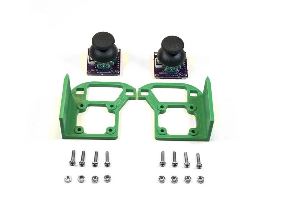
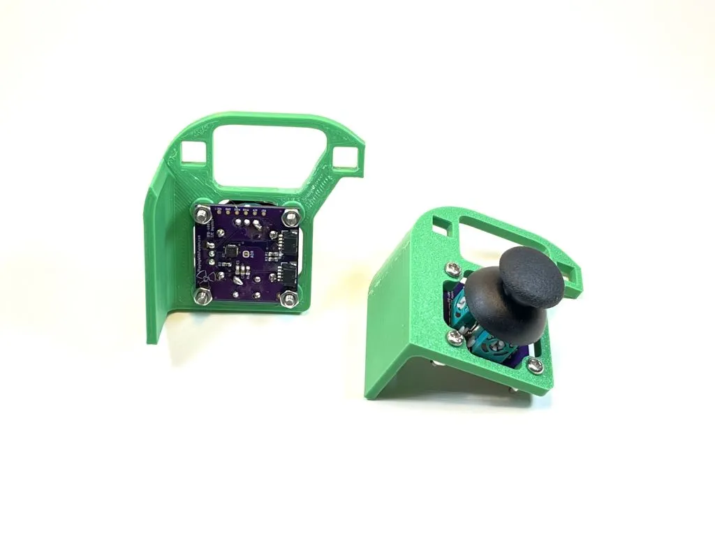
Assemble the joystick PCBs to the joystick bracket using 8 m3x12 screws and 8 m3 nuts. The QWIIC connectors should point away from the wall of the joystick bracket.
Step 4:
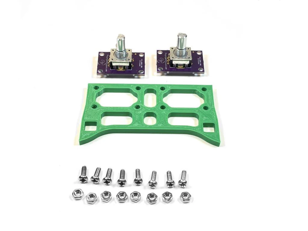
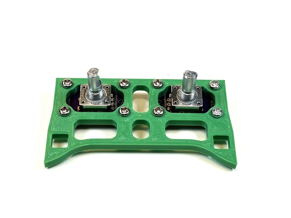
Assemble the encoder PCBs to the encoder bracket using 8 m3x8 screws and 8 m3 nuts.
Step 5:
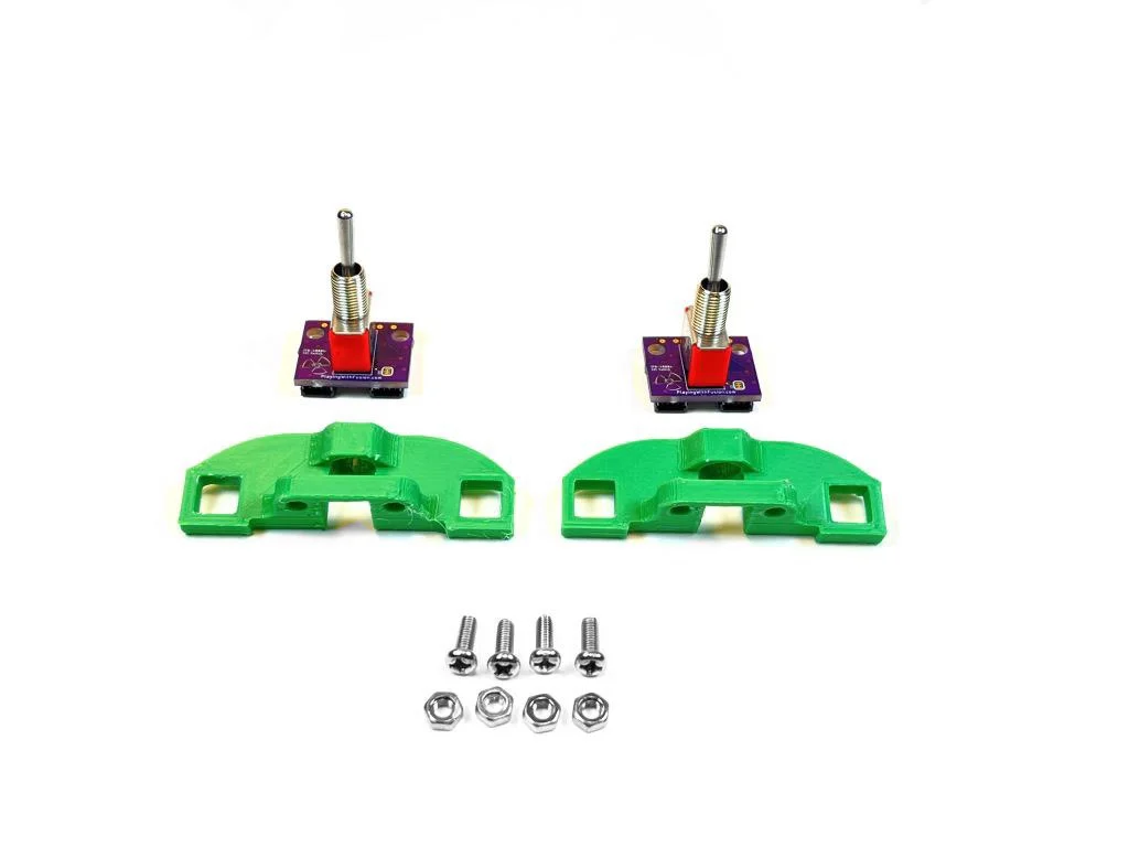
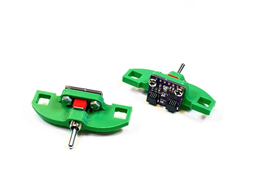
Assemble the switch PCBs to the switch brackets using 4 m3x8 screws and 4 m3 nuts.
Step 6:
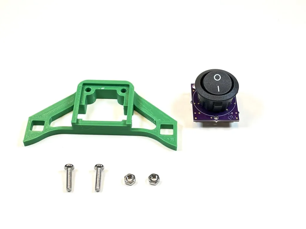
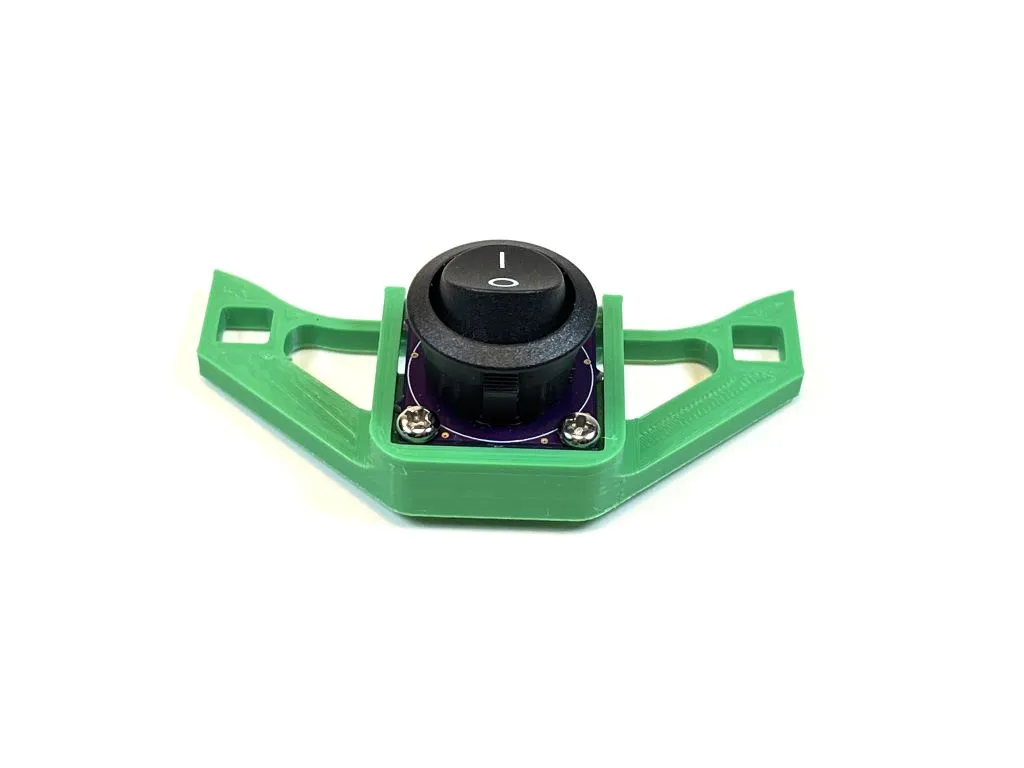
Assemble the power switch PCBs to the power switch bracket using 2 m3x12 screws and 2 m3 nuts.
Step 7:
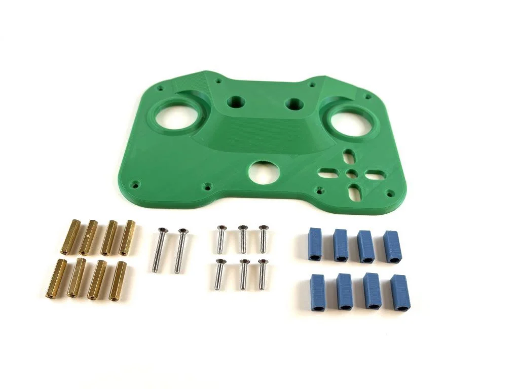
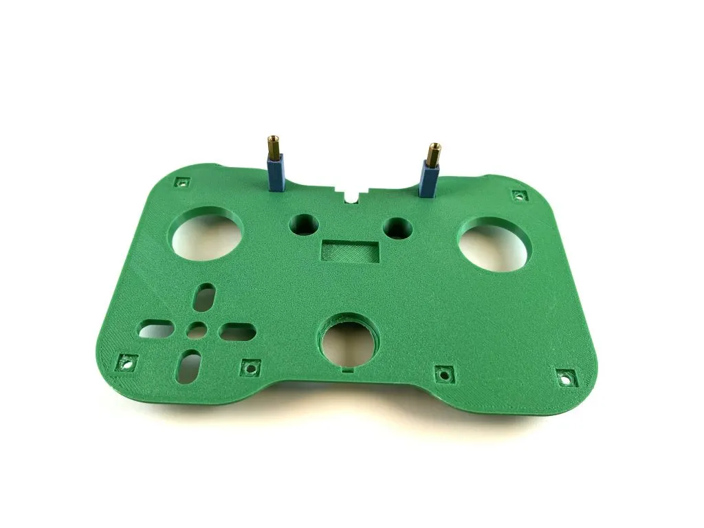
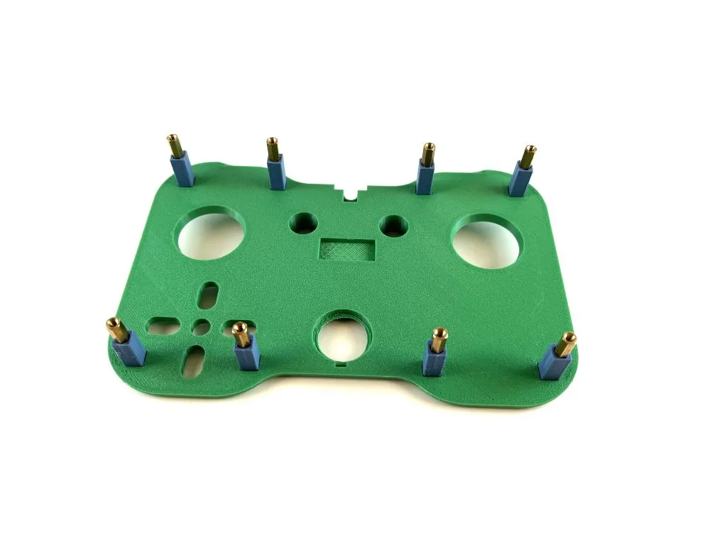
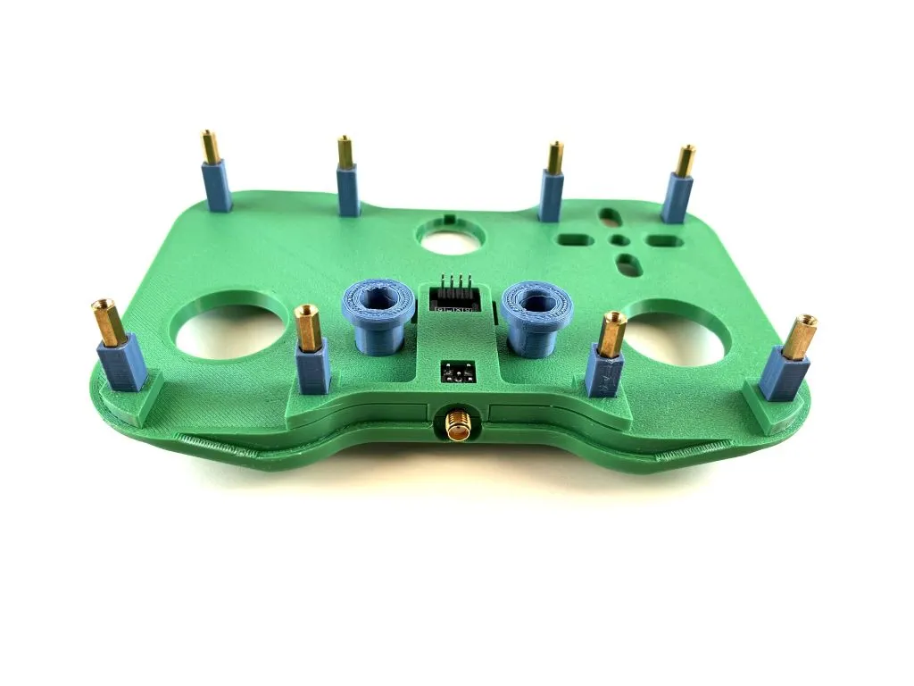
Using 6 m3x16 countersunk screws, 2 m3x20 countersunk screws and 8 m3x20 hex standoffs, fasten the 3D printed standoffs to the 3D printed top of the controller. Use the longer screws for the upper-middle holes. Ensure the standoffs are all aligned properly in the square slots on the underside of the 3D printed top.
Step 8:
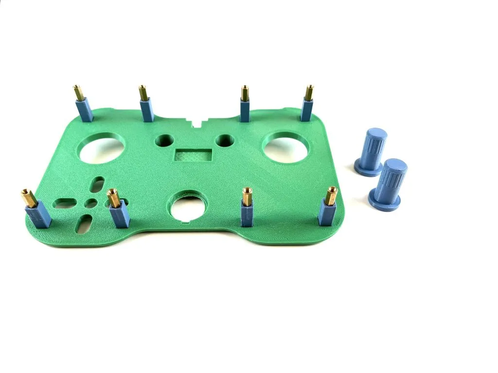
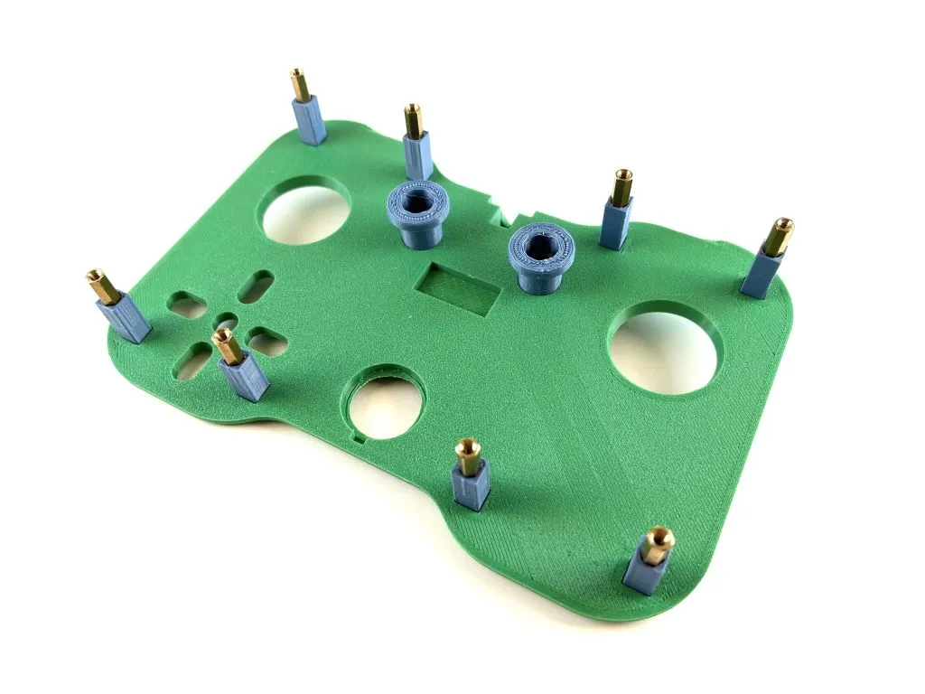
Insert the encoder knobs into the encoder knob holes.
Step 9:
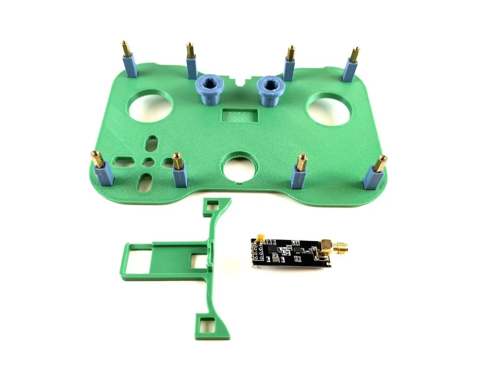
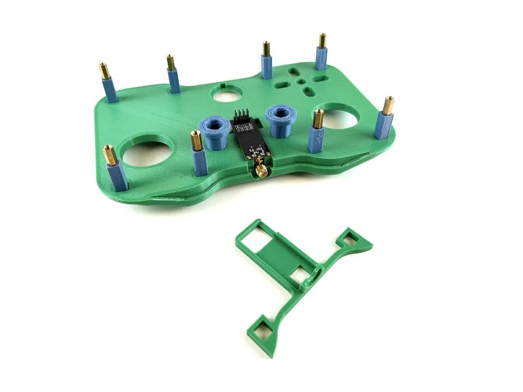
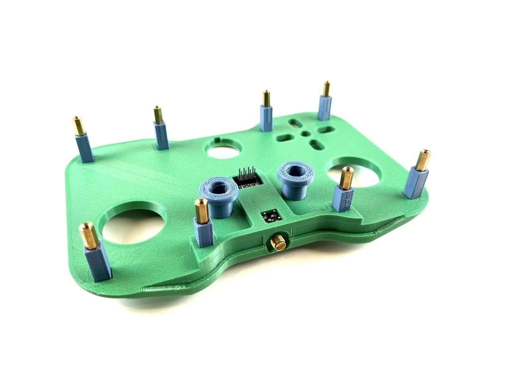
Place the radio module in its place. Fit the radio module enclosure around it.
Step 10:
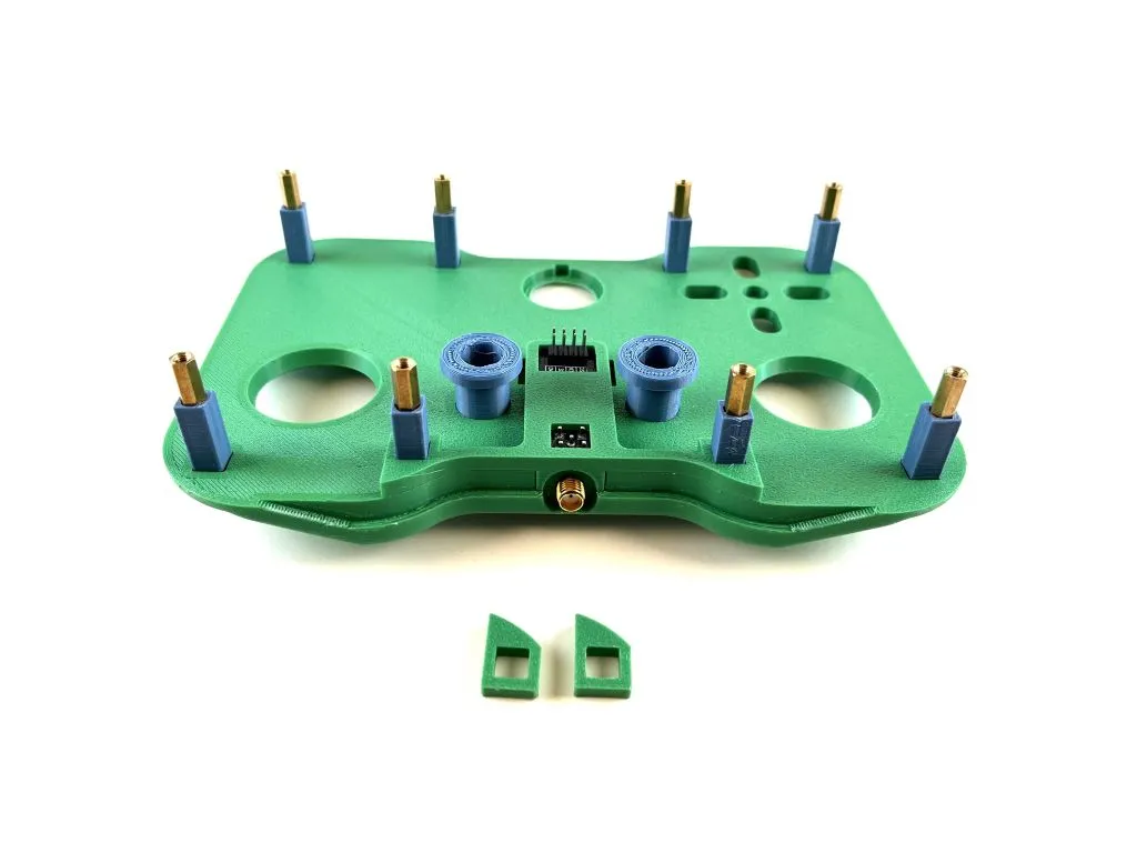
Slide two small sacers onto the standoffs to match the height of the radio module enclosure.
Step 11:

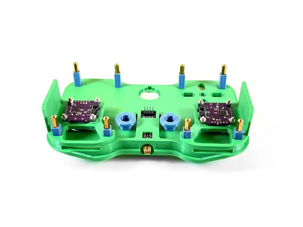
Place the assembeled joystick modules on the standoffs.
Step 12:
Add the remaining two small spacers on the outside standoffs on top of the joystick mount. Place the encoder mount assembly and place it on the center standoffs. The encoder knobs will need to slide into the 3D printed encoder knobs placed earlier. As the encoder mount assembly is slid into place, rotate the 3D printed encoder knobs until the metal encoder knobs find their place.
Step 13:
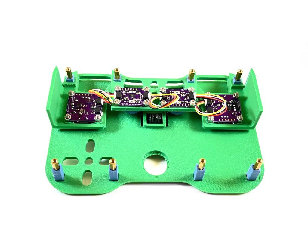
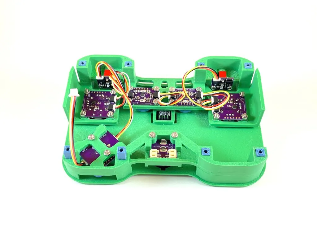
Use 3 QWIIC cables to connect each one of the interface boards. The left joystick is connected to the left encoder is connected to the right encoder is connected to the right joystick.
Step 14:
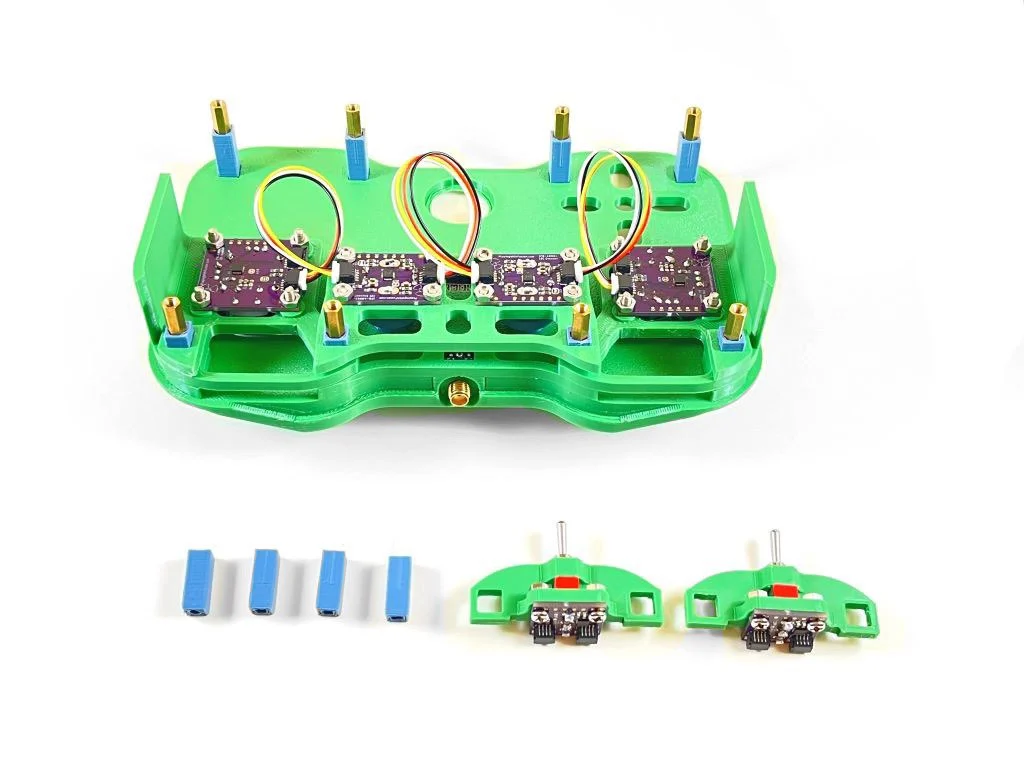
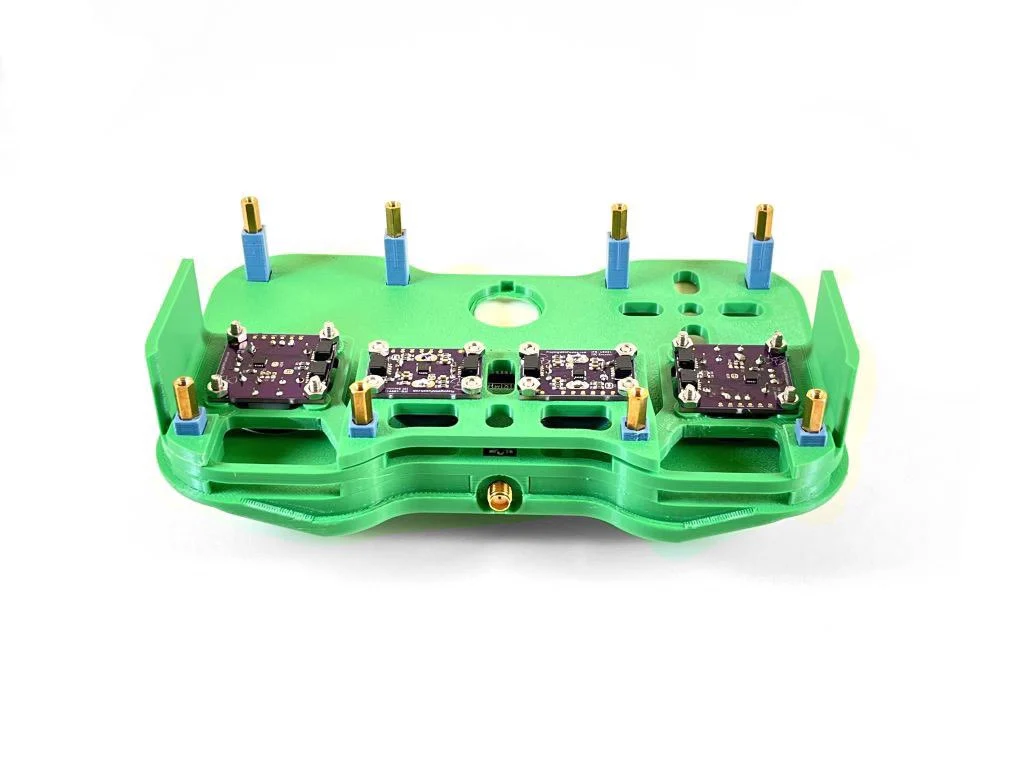
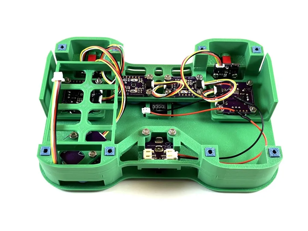
Slide four more 3D printed standoffs onto the hex standoffs. After this, slide the switch mount assemblies onto the standoffs. The QWIIC connectors on the PCBs should be pointed upwards (away from the 3D printed top).
Step 15:
Add 3 more QUIIC cables to connect the left switch PCB to the left joystick PCB and the right joystick PCB to the right switch PCB. The third cable should be plugged into the right switch PCB. The other end will be plugged in later.
Step 16:
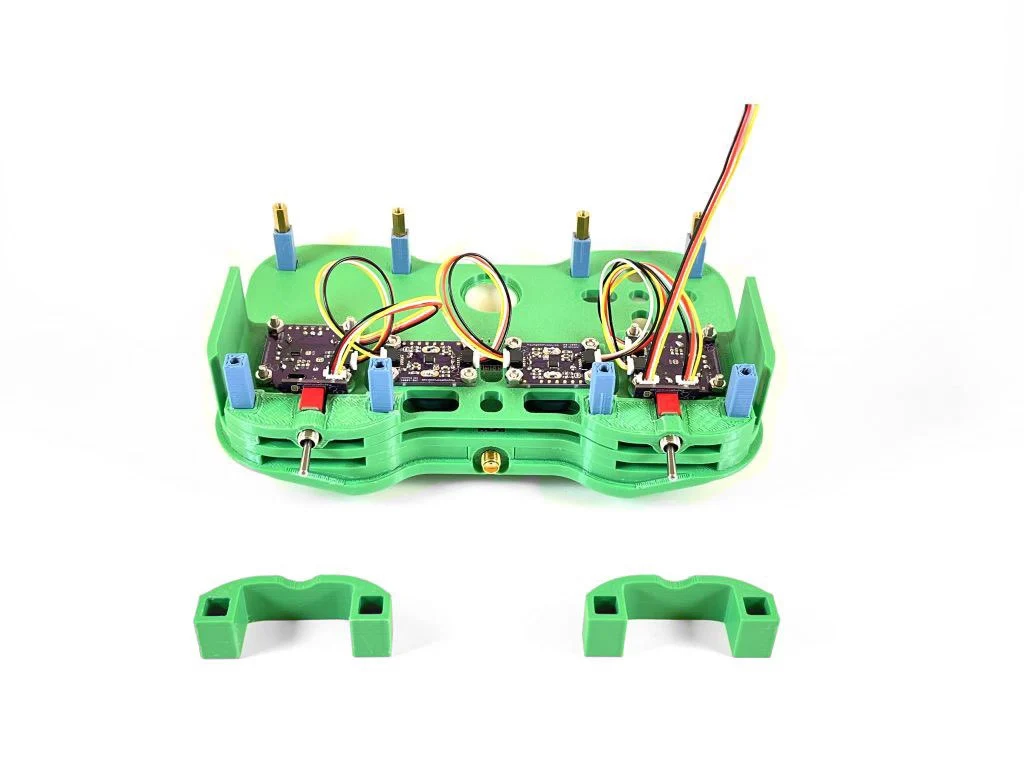
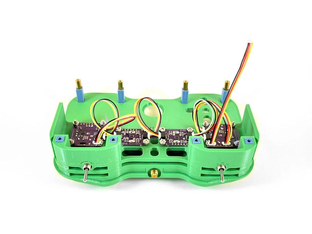
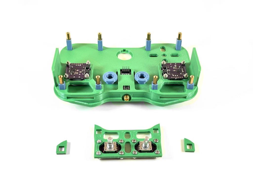
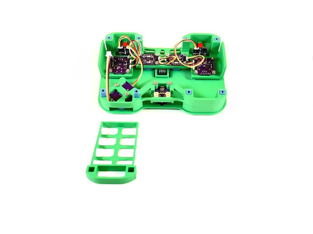
Slide the two mirrored switch spacers onto the 3D printed standoffs. These are the last parts that need to go on this end of the controller, so only a small sliver of the standoff should be raised above the top surface of the spacers.
Step 17:
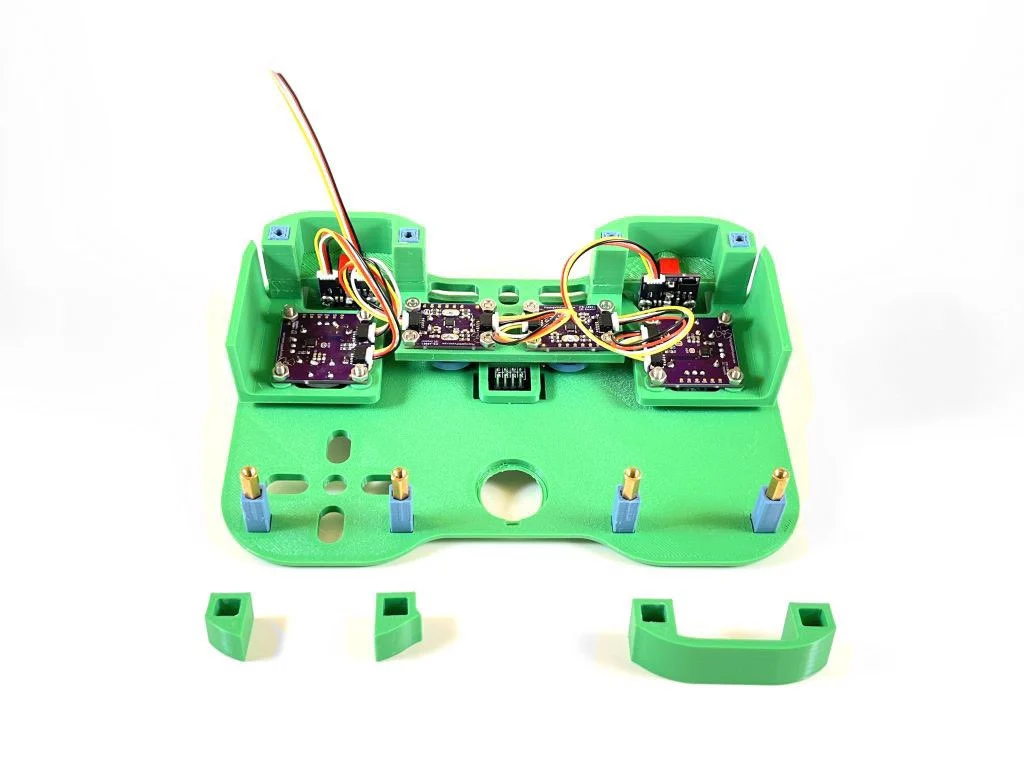
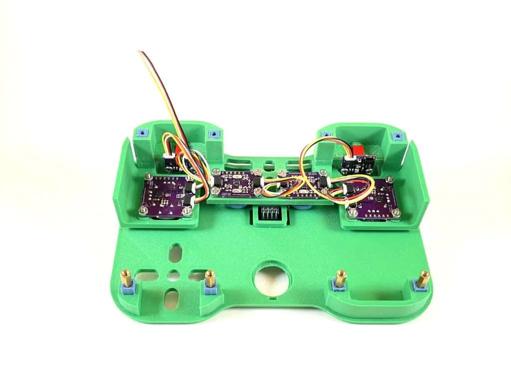
On the opposite side of the controller, place 3 spacers into their proper places on the 3D printed standoffs. Ensure the contour of the spacers matches the contour of the edge shape of controller’s top, like in the above image.
Step 18:
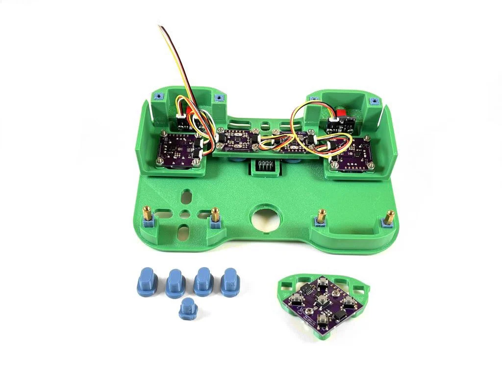
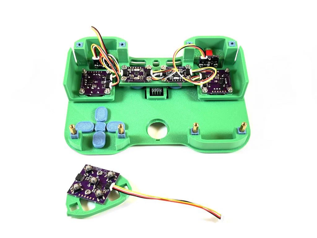
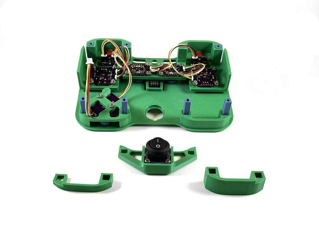
Place the 3D printed buttons into the button holes on the top. Add a QWIIC cable into the QWIIC connector on the button PCB, leaving the other end unconnected for now.
Step 19:
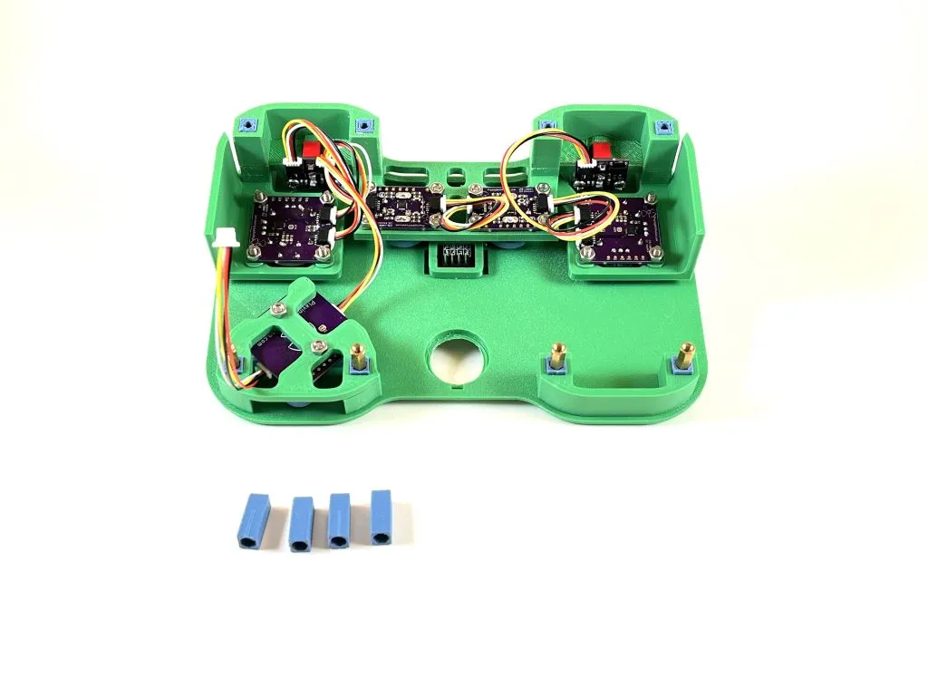
Place the last four standoffs onto the hex standoffs. Also, plug the unconnected QWIIC cable from the switch PCB into the QWIIC connector on the button PCB.
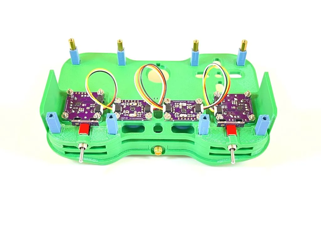
Step 20:
Slide the switch mount assembly into place. It may require some maneuvering to get the switch to fit into the switch hole on the top. Once it is in place, add the two 3D printed spacers.
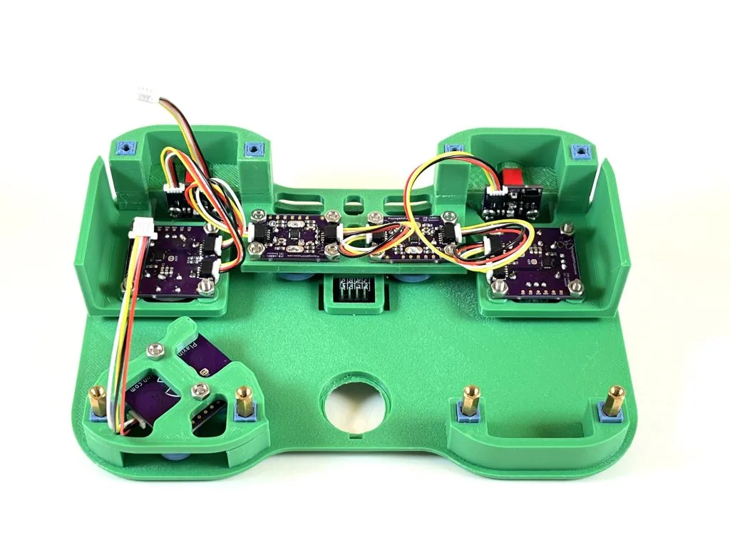
Step 21:
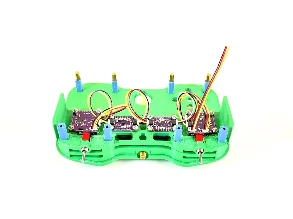
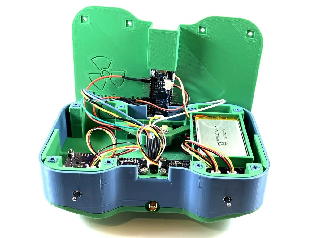
Slide the battery enclosure into the last open place on the standoffs. Plug one end of the JST cable into the terminal on the right side of the switch.
Step 22:
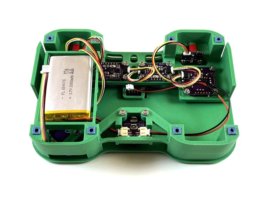
Set the rechargable battery into the battery enclosure. Feed the battery cable through an opening in the enclosure and plug it into the left terminal of the switch.
Step 23:
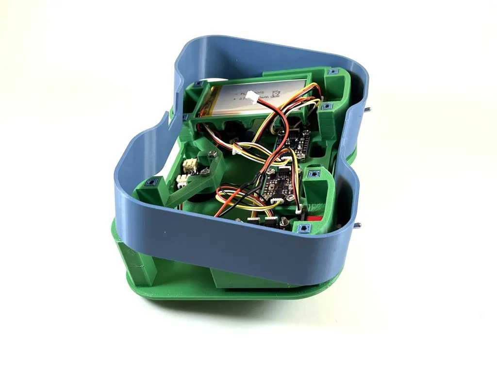
Utilize the flexibility of the outer wall to place it around the controller. It helps if the toggle switch levers are placed in their respective holes first, and then the other side is slid into place.
Step 24:
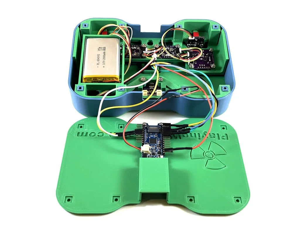
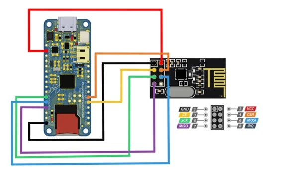
Make the remaining electrical connections. Plug the other end of JST connector into the R3aktor battery JST terminal. Connect each pin of the radio module to its respective pin on the R3aktor (see the above connection diagram).
- R3aktor -> NRF24L01
- GND -> GND
- 3V3 -> VCC
- D09 -> CE
- D10 -> CSN
- SCK -> SCK
- MOSI -> MOSI
- MISO -> MISO
Step 25:
Plug the loose end of the last QWIIC cable into the R3aktor board.
Step 26:
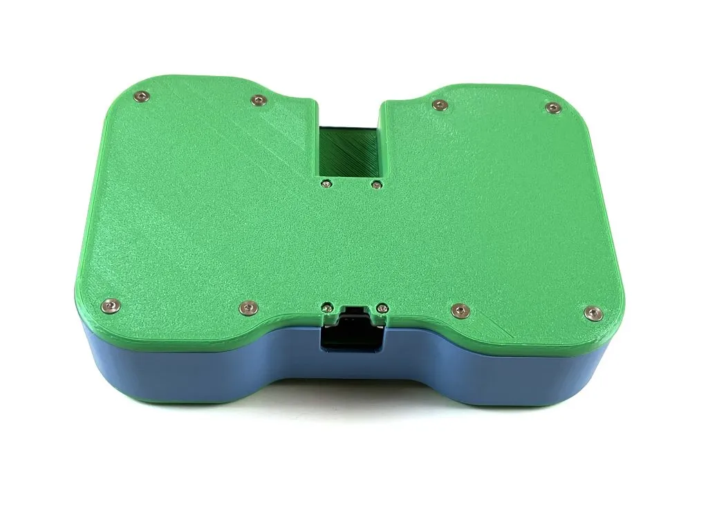
Fit the 3D printed bottom into place. Make sure all wires are stored safely inside the controller and are not pinched. Use 8 M3x16 countersunk screws to fasten the bottom into place.
Done
Congradulations! The controller is now ready for programming.
Controller Programming
Connect the controller to a computer using a USB-C cable. Download and open the RC Transmitter code in the Arduino IDE. If you have not already, follow the instructions for setting up the Arduino IDE to work with the R3aktor board. Once the code is opened, click on the RC_Transmitter.ino tab. Upload this code to the controller.
- /***************************************************************************
- * File Name: RC_Transmitter.ino
- * Processor/Platform: PwFusion R3aktor M0 (tested)
- * Development Environment: Arduino 2.1.1
- *
- * Designed to collect information from Playing with Fusion I2C interface boards
- * and write them to a NRF24L01 radio.
- *
- * Copyright ? 2023 Playing With Fusion, Inc.
- * SOFTWARE LICENSE AGREEMENT: This code is released under the MIT License.
- *
- * Permission is hereby granted, free of charge, to any person obtaining a
- * copy of this software and associated documentation files (the "Software"),
- * to deal in the Software without restriction, including without limitation
- * the rights to use, copy, modify, merge, publish, distribute, sublicense,
- * and/or sell copies of the Software, and to permit persons to whom the
- * Software is furnished to do so, subject to the following conditions:
- *
- * The above copyright notice and this permission notice shall be included in
- * all copies or substantial portions of the Software.
- *
- * THE SOFTWARE IS PROVIDED "AS IS", WITHOUT WARRANTY OF ANY KIND, EXPRESS OR
- * IMPLIED, INCLUDING BUT NOT LIMITED TO THE WARRANTIES OF MERCHANTABILITY,
- * FITNESS FOR A PARTICULAR PURPOSE AND NONINFRINGEMENT. IN NO EVENT SHALL THE
- * AUTHORS OR COPYRIGHT HOLDERS BE LIABLE FOR ANY CLAIM, DAMAGES OR OTHER
- * LIABILITY, WHETHER IN AN ACTION OF CONTRACT, TORT OR OTHERWISE, ARISING
- * FROM, OUT OF OR IN CONNECTION WITH THE SOFTWARE OR THE USE OR OTHER
- * DEALINGS IN THE SOFTWARE.
- * **************************************************************************
- * REVISION HISTORY:
- * Author Date Comments
- * N. Johnson 2023Sep30 Original version
- *
- * Playing With Fusion, Inc. invests time and resources developing open-source
- * code. Please support Playing With Fusion and continued open-source
- * development by buying products from Playing With Fusion!
- ***************************************************************************/
- // Include the radio module libraries
- #include <RF24.h>
- #include <RF24_config.h>
- #include <nRF24L01.h>
- #include <printf.h>
- // Include the PwFusion I2C Interface board libraries
- #include <PwFusion_I2C_Toggle_Arduino_Library.h>
- #include <PwFusion_I2C_Joystick_Arduino_Library.h>
- #include <PwFusion_I2C_Encoder_Arduino_Library.h>
- #include <PwFusion_I2C_Buttons_Arduino_Library.h>
- // Define the radio pins
- #define CE_PIN 9
- #define CSN_PIN 10
- // Address definitions
- uint8_t ADR_ENC_A = 0x01;
- uint8_t ADR_ENC_B = 0x02;
- uint8_t ADR_JOY_A = 0x03;
- uint8_t ADR_JOY_B = 0x04;
- uint8_t ADR_BTN_B = 0x05;
- uint8_t ADR_BTN_A = 0x06;
- uint8_t ADR_SW_A = 0x07;
- uint8_t ADR_SW_B = 0x08;
- // Create new instances of the objects for each I2C board
- Joystick joyA;
- Joystick joyB;
- Encoder encA;
- Encoder encB;
- Buttons btnA;
- Buttons btnB;
- Switch swA;
- Switch swB;
- // Define the address for the radio
- const uint64_t pipe = 0x01;
- // Define an array for storing and sending data
- uint8_t data[13];
- // Initialize the radio object
- RF24 radio(CE_PIN, CSN_PIN);
- void setup() {
- Serial.begin(9600);
- // Initialize each I2C interface board object
- joyA.begin(ADR_JOY_A);
- joyB.begin(ADR_JOY_B);
- encA.begin(ADR_ENC_A);
- encB.begin(ADR_ENC_B);
- btnA.begin(ADR_BTN_A);
- btnB.begin(ADR_BTN_B);
- swA.begin(ADR_SW_A);
- swB.begin(ADR_SW_B);
- // Start the radio
- radio.begin();
- radio.openWritingPipe(pipe);
- }
- void loop() {
- // Store each piece of data from the I2C boards in the array
- data[0] = joyA.getVRX();
- data[1] = joyA.getVRY();
- data[2] = joyA.getSW();
- data[3] = joyB.getVRX();
- data[4] = joyB.getVRY();
- data[5] = joyB.getSW();
- data[6] = encA.getBtnState();
- data[7] = encA.getCount();
- data[8] = encB.getBtnState();
- data[9] = encB.getCount();
- data[10] = btnA.getBtn();
- data[11] = swA.getState();
- data[12] = swB.getState();
- //Print out the values of the interface boards to the Serial Monitor
- Serial.print("JOY_A x: ");
- Serial.print(data[0]);
- Serial.print(" | ");
- Serial.print("JOY_A y: ");
- Serial.print(data[1]);
- Serial.print(" | ");
- Serial.print("JOY_A sw: ");
- Serial.print(data[2]);
- Serial.print(" | ");
- Serial.print("JOY_B x: ");
- Serial.print(data[3]);
- Serial.print(" | ");
- Serial.print("JOY_B y: ");
- Serial.print(data[4]);
- Serial.print(" | ");
- Serial.print("JOY_B sw: ");
- Serial.print(data[5]);
- Serial.print(" | ");
- Serial.print("ENC_A sw: ");
- Serial.print(data[6]);
- Serial.print(" | ");
- Serial.print("ENC_A count: ");
- Serial.print(data[7]);
- Serial.print(" | ");
- Serial.print("ENC_B sw: ");
- Serial.print(data[8]);
- Serial.print(" | ");
- Serial.print("ENC_B count: ");
- Serial.print(data[9]);
- Serial.print(" | ");
- Serial.print("BTN_A btn: ");
- Serial.print(data[10]);
- Serial.print(" | ");
- Serial.print("SW_A state: ");
- Serial.print(data[11]);
- Serial.print(" | ");
- Serial.print("SW_B state: ");
- Serial.print(data[12]);
- Serial.print(" | ");
- Serial.println();
- // Write the array to the radio address.
- radio.write(&data, sizeof(data));
- }
Operating Instructions
To turn the controller on, flip the power switch. A light should appear to indicate the controller is recieving power. When charging the controller, the power switch must be in the on position.
Reciever Programming
The controller must talk to a receiver to interface with any project. All the receiver needs to consist of is a controller board (like a r3aktor or an Arduino) and an nrf24l01 radio module. This controller board will receive a packet of data from the controller and store it in an array. Each array value represents the output values from a component within the controller. If the given code (RC_Transmitter.ino) was used, the array is structured like the following list:
- data[0] = joystick A x-axis
- data[1] = joystick A y-axis
- data[2] = joystick A button
- data[3] = joystick B x-axis
- data[4] = joystick B y-axis
- data[5] = joystick B button
- data[6] = encoder A button
- data[7] = encoder A count
- data[8] = encoder B button
- data[9] = encoder B count
- data[10] = buttons state
- data[11] = switch A state
- data[12] = switch B state
The following code provides an example of a reciever. This code recieves the data from the transmitter and uses those values to set the speeds and directions of drive motors for a tracked base (still a work in progress).
- // Include the required libraries for communication with the nrf module
- #include <SPI.h>
- #include <nRF24L01.h>
- #include <RF24.h>
- // CE and CSN pin definitions
- #define CE_PIN 7
- #define CSN_PIN 8
- // Motor pin definitions
- #define Ap1 3
- #define Ap2 5
- #define Bp1 6
- #define Bp2 9
- #define Cp1 2
- #define Cp2 4
- // Dead zone for input values
- int D_ZONE = 2;
- // Joystick position definitions
- float joyAx = 0;
- float joyAy = 0;
- float joyBx = 0;
- float joyBy = 0;
- // Define the address for RF communication
- const uint64_t pipe = 0x01;
- // Define the package size to receive.
- uint8_t data[13];
- // Define the new radio object
- RF24 radio(CE_PIN, CSN_PIN);
- void setup() {
- pinMode(Ap1, OUTPUT);
- pinMode(Ap2, OUTPUT);
- pinMode(Bp1, OUTPUT);
- pinMode(Bp2, OUTPUT);
- pinMode(Cp1, OUTPUT);
- pinMode(Cp2, OUTPUT);
- // Make sure all motors are off
- digitalWrite(Ap1, LOW);
- digitalWrite(Ap2, LOW);
- digitalWrite(Bp1, LOW);
- digitalWrite(Bp2, LOW);
- digitalWrite(Cp1, LOW);
- digitalWrite(Cp2, LOW);
- Serial.begin(9600);
- delay(1000);
- // Initialize the radio for recieving
- Serial.println("Nrf24L01 Receiver Starting");
- radio.begin();
- radio.openReadingPipe(1,pipe);
- radio.startListening();
- }
- void loop() {
- // This demonstraits how to recieve the inputs from the RC Transmitter.
- if ( radio.available() ) {
- // Read the data from the radio and store it in the data array
- radio.read(data, sizeof(data));
- // Uncomment to see controller values in the Serial Monitor
- // Print out each value from data to the Serial Monitor
- // for (int i = 0; i < 13; i++) {
- // Serial.print(data[i]);
- // Serial.print("\t");
- // }
- // Serial.println();
- // Retrieve, map, and assign the joystick position values from the data array
- joyAx = map(data[0], 0, 255, -255, 255);
- joyAy = map(data[1], 0, 255, -255, 255);
- joyBx = map(data[3], 0, 255, -255, 255);
- joyBy = map(data[4], 0, 255, -255, 255);
- // Functions to set motor speeds and directions
- set_motor_pwm(joyAy, Ap1, Ap2);
- set_motor_pwm(joyBy, Bp1, Bp2);
- set_motor(joyAx, Cp1, Cp2);
- } else {
- Serial.println("Transmitter unavailable");
- }
- }
- void set_motor_pwm(int pwm, int pin1, int pin2) {
- if (pwm < -2) {
- analogWrite(pin1, -1 * pwm);
- digitalWrite(pin2, LOW);
- Serial.println("Forward");
- } else if (pwm > 2) {
- digitalWrite(pin1, LOW);
- analogWrite(pin2, pwm);
- Serial.println("Put it in reverse, Terry!");
- } else {
- digitalWrite(pin1, LOW);
- digitalWrite(pin2, LOW);
- }
- }
- void set_motor(int in, int pin1, int pin2) {
- if (in < -10) {
- digitalWrite(pin2, LOW);
- digitalWrite(pin1, HIGH);
- } else if (in > 10) {
- digitalWrite(pin2, HIGH);
- digitalWrite(pin1, LOW);
- } else {
- digitalWrite(pin2, LOW);
- digitalWrite(pin1, LOW);
- }
- }
 R3actor M0 Logger with SD Socket and Battery Charger