Product Categories
- Arduino Shields
- Breakout Boards
- CAN (Controller Area Network)
- Connectors and Interconnect
- Drivers, DACs & Outputs
- FIRST Robotics Competition
- Formula SAE
- Hardware
- Interface and Logging
- Power Supplies and Distribution
- Qwiic Connect System
- R3aktor Data Acquisition
- Sensors
- Software
- Switches, Encoders, & Buttons
- Temperature Measurement
- Wire
- Discontinued
Tech Article Categories
Posted: March 6, 2025
Modified: March 6, 2025
Home > Tech Article Categories > R3actor and Arduino > Battery Charging and Status with R3aktor
Battery Charging and Status with R3aktor
Introduction
All R3aktor products include an integrated LiPo battery charger which can be connected to a single battery cell. The R3aktor will automatically charge a connected battery anytime power is provided through the USB-C connector. Once USB power is removed R3aktor will automatically switch over to using the battery for power.
Battery voltage can be monitored directly by reading the ADC_BATTERY analog input from within the Arduino IDE
IMPORTANT NOTE!
Before connecting the LiPo battery to the R3aktor, make sure the polarity of the battery matches the polarity of the R3aktor’s battery plug. The connector is keyed, which means it can only insert in one orientation.
Hardware Setup
For this project, you will need:
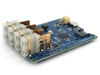
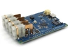
- (x1) R3aktor M0 Logger Board
- (x1) USB-C cable
- (x1) 3.7v LiPo battery
- (x4) 5mm LEDs
- (x4) 220Ω Resistors
- (x5) Male to female jumper cables
Voltage Measurement through Serial Monitor
Connect the R3aktor to your computer via the USB-C cable and then insert the battery into the R3aktor.
When the battery is connected to the R3aktor and the R3aktor is connected to a power source like a computer via the USB-C cable, the battery will begin charging. Otherwise, the battery will be the power source of the R3aktor.

Open the Arduino IDE on your computer and create a new sketch. Copy and paste this code:
- void setup() {
- Serial.begin(9600);
- }
- void loop() {
- // analogRead() returns the battery voltage in ADC counts (10-bit)
- // Multiply by (2 * 3.3) / 1024 to convert from counts to voltage in Volts
- float voltage = analogRead(ADC_BATTERY) * 2 * 3.3/1024;
- Serial.println(voltage);
- // Wait one second
- delay(1000);
- }
Upload the code to the R3aktor board. Open the serial monitor by selecting Tools -> Serial Monitor or by selecting the serial monitor icon in the upper left corner.
In the serial monitor, you will see the voltage of the battery being printed. It should be slowly rising because the battery is being charged. If you could read this value without the R3aktor being connected to a computer, you would see it slowly decrease.
LED Battery Level Indicator
To create a battery level indicator for when the R3aktor is not connected to a computer, set up the circuit depicted below.
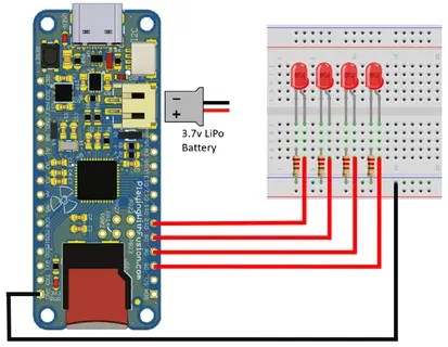
Remember to disconnect the battery before connecting components and wires to the R3aktor board.
Each LED will be connected to digital pins 5, 6, 9, and 10.
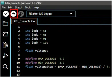
Once you have connected each LED to the R3aktor, go back to the Arduino IDE and create a new sketch. Copy and paste this code:
- int led1 = 5;
- int led2 = 6;
- int led3 = 9;
- int led4 = 10;
- float voltage;
- #define MAX_VOLTAGE 4.2
- #define MIN_VOLTAGE 3.2
- float voltageStep = (MAX_VOLTAGE - MIN_VOLTAGE) / 4;
- void setup() {
- // Configure the four LED pins as output and turn each off
- pinMode(led1, OUTPUT);
- pinMode(led2, OUTPUT);
- pinMode(led3, OUTPUT);
- pinMode(led4, OUTPUT);
- digitalWrite(led1, LOW);
- digitalWrite(led2, LOW);
- digitalWrite(led3, LOW);
- digitalWrite(led4, LOW);
- Serial.begin(9600);
- }
- void loop() {
- voltage = getVoltage();
- Serial.println(voltage);
- updateStatusLEDs(voltage);
- delay(1000);
- }
- void updateStatusLEDs(float value) {
- // Check the voltage and update the status LEDs accordingly.
- if (value >= MIN_VOLTAGE + (0*voltageStep)) digitalWrite(led1, HIGH); else digitalWrite(led1, LOW);
- if (value >= MIN_VOLTAGE + (1*voltageStep)) digitalWrite(led2, HIGH); else digitalWrite(led2, LOW);
- if (value >= MIN_VOLTAGE + (2*voltageStep)) digitalWrite(led3, HIGH); else digitalWrite(led3, LOW);
- if (value >= MIN_VOLTAGE + (3*voltageStep)) digitalWrite(led4, HIGH); else digitalWrite(led4, LOW);
- }
- float getVoltage() {
- return (analogRead(ADC_BATTERY) * 2 * 3.3/1024);
- }
Connect your R3aktor to your computer via the USB-C cable and upload this code by selecting the upload arrow.
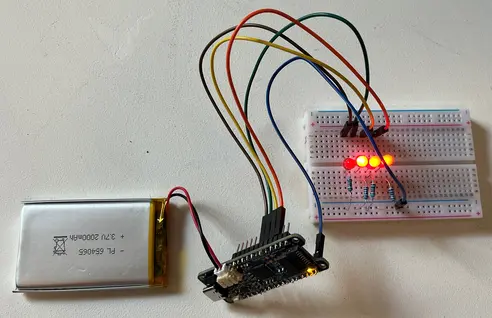
When the battery is connected to the R3aktor board, the LEDs will light up to indicate the voltage level of the battery, which is a good indicator of its charge level.
 R3actor M0 Logger with SD Socket and Battery Charger
 R3aktor Core J-Type Thermocouple Data Acquisition Board
 R3aktor Core K-Type Thermocouple Data Acquisition Board
 R3aktor Core T-Type Thermocouple Data Acquisition Board
 R3aktor Core Universal Thermocouple Data Acquisition Board
 R3aktor Core PT100 RTD Temperature Data Acquisition Board
 R3aktor Core PT1000 RTD Temperature Data Acquisition Board