Product Categories
- Arduino Shields
- Breakout Boards
- CAN (Controller Area Network)
- Connectors and Interconnect
- Drivers, DACs & Outputs
- FIRST Robotics Competition
- Formula SAE
- Hardware
- Interface and Logging
- Power Supplies and Distribution
- Qwiic Connect System
- R3aktor Data Acquisition
- Sensors
- Software
- Switches, Encoders, & Buttons
- Temperature Measurement
- Wire
- Discontinued
Tech Article Categories
Table of Contents
Posted: March 6, 2025
Modified: March 6, 2025
Home > Tech Article Categories > R3actor and Arduino > Servo Control with R3aktor
Servo Control with R3aktor
Introduction
Hobby servos are a great way to add physical motion to your projects. They typically have three wires: 5V power, ground, and signal. The servo position is commanded by electrical pulses on the signal wire. Short pulses (about 1ms) drive the servo all the way one direction, while long pulses (2ms) drive it to the other side. A 'centered' pulse (1.5ms) commands the servo to move to the center position, between the two end stops.
R3aktor is capable of driving the servo signal wire directly. Due to possible current requirements, the servo itself should be powered by a separate power supply rather than the 5V USB power from a PC to avoid damaging the computer's port.
Hardware Setup
For this project, you will need:
- (x1) R3aktor M0 Logger Board
- (x1) USB-C cable
- (x1) Servo motor
- (x1) 5V breadboard power supply
- (x1) AC to DC wall wart
- (x1) Solderless breadboard
- (x3) Male to male jumper cables
- (x2) Male to female jumper cables
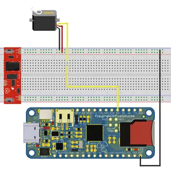
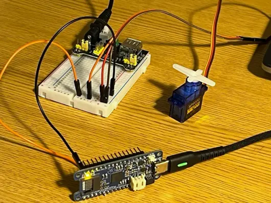
Place the breadboard power supply into the breadboard. Connect the wires of the servo to their respective locations on the breadboard. Red to the red (+) power rail on the breadboard, brown to the blue (-) power rail on the breadboard, and orange to any location on the breadboard. Connect the R3aktor GND pin to the blue (-) power rail on the breadboard. Connect digital pin 9 (D9) on the R3aktor board to the same rail as the servo’s orange wire is connected to. Once complete, your circuit should look like the diagram below. Confirm that the GND pin on the breadboard power supply module is in the blue (-) rail and the VCC pin on the power supply is in the red (+) rail.
Initial Software
Open the Arduino IDE. For this project, you will need to utilize the Arduino Servo library which comes pre-installed with the IDE, so there is no library installation you need to do. Copy and paste this code into a new sketch:
- #include <Servo.h>
- Servo servo; // Create a servo object
- int d = 1; // Sweep speed delay value
- void setup() {
- servo.attach(9); // Attach the servo to PWM pin 9
- }
- void loop() {
- for (int i = 0; i <= 180; i++) { // Sweep from 0 to 180
- servo.write(i);
- delay(d);
- }
- delay(1000);
- for (int i = 180; i >= 0; i--) { // Sweep from 180 to 0
- servo.write(i);
- delay(d);
- }
- delay(1000);
- }
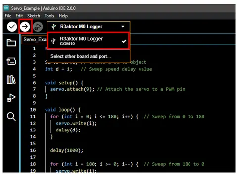
Connect the R3aktor board to your computer with the USB-C cable.
In the Arduino IDE, select the R3aktor board. Then select upload.
Most breadboard power supply modules will have a switch on them. Once the power supply module is connected to an AC to DC wall wart, the switch can be turned on and the servo motor will begin to sweep back and forth, stopping for a moment between each movement. You may notice that the movement speed of the servo is constant at all angles. This can lead to a “jerkiness” effect when changing directions in a short period of time.
Now, comment out the delay() statements on lines 15 and 22 to see this effect in action:
- //delay(1000);
- for (int i = 180; i >= 0; i--) { // Sweep from 180 to 0
- servo.write(i);
- delay(d);
- }
- //delay(1000);
As you can see, the servo is unable to reach the desired range of motion, and the rapid change of direction causes unwanted vibrations. To fix this, a technique known as “servo dampening” can be applied. This method decreases the servo’s speed as it nears its goal angle, decreasing the inertia of the motor and leading to the change in direction causing less vibrations.
Because this is a common issue, there is already a library that allows you to control a servo’s acceleration. This library is called “ServoEasing”. To utilize it, you will first need to install it.
Reducing Jerkiness
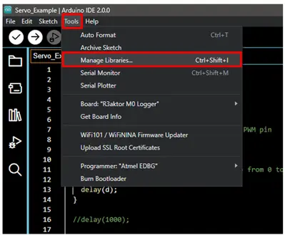
Open the library manager in the Arduino IDE by selecting Tools -> Manage Libraries…
In the search box, type ServoEasing
Hover your mouse over the ServoEasing library and select install.
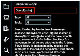
Then, wait for the process to complete.
Copy this code to your Arduino IDE:
- #include <Servo.h>
- #include <ServoEasing.hpp>
- ServoEasing servo; // Create a servo object
- void setup() {
- Serial.begin(9600);
- servo.attach(9, 45); // Attach the servo to a PWM pin
- delay(500);
- }
- void loop() {
- Serial.println("Bounce - out");
- moveServo(EASE_BOUNCE_OUT);
- Serial.println("Cubic - in and out");
- moveServo(EASE_CUBIC_IN_OUT);
- Serial.println("Circular Bouncing");
- moveServo(EASE_CIRCULAR_BOUNCING);
- Serial.println("Sine bouncing");
- moveServo(EASE_SINE_BOUNCING);
- Serial.println("Quadratic bouncing");
- moveServo(EASE_QUADRATIC_BOUNCING);
- }
- void moveServo(uint_fast8_t movementType){
- for (int i = 0; i <=2; i++){
- Serial.print(" "); Serial.println(i);
- servo.setEasingType(movementType); // Set the easing type to the passed value
- servo.easeTo(170, 120);
- servo.easeTo(10, 120);
- }
- }
Make sure to select the R3aktor board and select upload.
This code goes through a few options of controlling servo movement allowed by the ServoEasing library. Each movement type has its own benefits, it all depends on the project requirements.
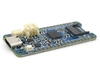 R3actor M0 Logger with SD Socket and Battery Charger
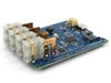
 R3aktor Core J-Type Thermocouple Data Acquisition Board
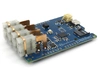
 R3aktor Core K-Type Thermocouple Data Acquisition Board
 R3aktor Core T-Type Thermocouple Data Acquisition Board
 R3aktor Core Universal Thermocouple Data Acquisition Board
 R3aktor Core PT100 RTD Temperature Data Acquisition Board
 R3aktor Core PT1000 RTD Temperature Data Acquisition Board